Compute Center
The “Green IT Cube” on the GSI/FAIR campus is one of the most powerful scientific data centers in the world. At the same time, it sets standards in IT technology and energy saving. Following section provides an overview on the Green Cube cooling system and power distribution.
Construction
The Green Cube was inaugurated in January 2016 after a construction period of one year. The form of the Green Cube measures 27×30×22 m with six floors and an adjacent technical building including cooling towers. The floorspace of 4645 m² provides room for 768 standard 19” computer racks. In the final expansion the infrastructure enables a cooling capacity of 12 MW with a designed PUE 1 smaller the 1.07. In December 2015 a technical acceptance test with a simulated load up to 2.3 MW (using heating dummies in the racks) demonstrated an average PUE of 1.051. Waste heat is utilized for the nearby office building and canteen.
The GreenCube is in the process of a multiple stages expansion after the initial start-up of the 5th and 6th floors. In 2022 the REACT-EU program 2 funded the next stage to prepare the infrastructure for the 3th and 4th floor. In 2023 a significant part of the Virgo compute cluster moved into the 4th floor. Since then the cluster is distributed over all three floors of the Green Cube making full use of the three-dimensional architecture of the computing center for cabling the InfiniBand high-performance network.
Cooling System
Thanks to a special cooling system the GreenCube is particularly energy and cost efficient. Instead of air, the compute racks are cooled with water. As a result, the energy used for cooling corresponds to less than seven percent of the electrical power used for computing. The water cooling solutions is build into the backdoor of the computer cabinets and alleviates the need for room temperature regulation inside the GreenCube. The heat-exchanger in the rack backdoor is completely passive. The air-flow thru the heat-exchange is created by the fans within the computer chassis. Since 2018 the GreenCube is certified with the Blue Angel Ecolabel 3 for energy efficiency.
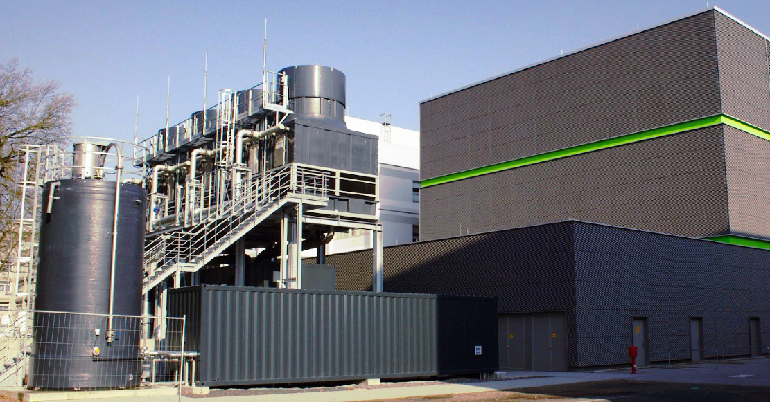
The outdoor cooling towers Figure 1 are positioned adjacent to the Green Cube and connect into the facility by huge pipes. These link the evaporation towers via the primary pumps with the heat-exchange and the internal water circuit within the Green Cube building. The container in the front left houses a water purification system connected to a reservoir used to replenish evaporated water lost by the cooling process. Right to the cooling towers in Figure 1 is the technical building for the water pumps and heat-exchange.
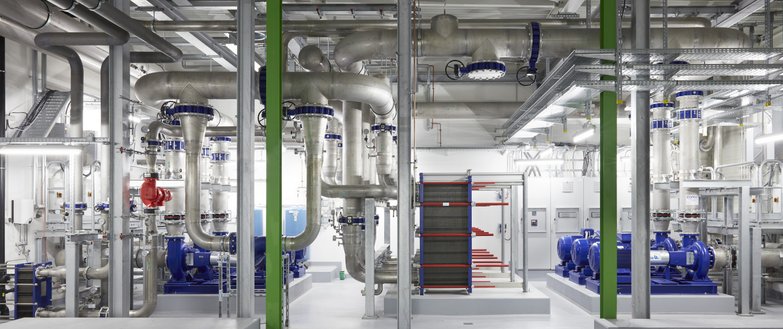
Figure 2 shows the pumping infrastructure for the 5th and 6th floor. In its final development the Green Cube will have three completely independent cooling systems each connected to two different floors. Basically three distinct computing centers in terms of cooling are stacked on top of each other. Figure 2 shows one of these cooling circuits build with a three line configuration for redundancy. The blue (primary) pumps on the right side connect the outdoor cooling towers to the heat-exchange. The heat-exchange are the big black blocks in the center of the picture. The (secondary) pumps on the left side connect with the internal water circuit supplying cold water to the compute cabinets. Typical operations conditions move 600 m³ of water per hour with a differential pressure of 150 millibar. The water temperature inside the Green Cube works within 16°C – 19°C.
Power Distribution
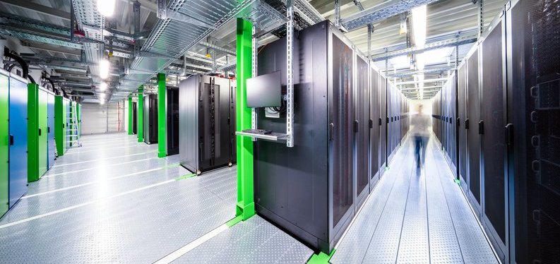
The power supply for the Green Cube is completely redundant including connection to primary utility power. There is no necessity of additional UPS (uninterruptible power source) 4 facilities based on on-site generators or backup batteries. Figure 3 shows a single floor in the Green Cube to illustrate the power distribution to the individual racks. The power transformers used to convert high-voltage power into lower voltages are located on the left side. Each computer cabinet row on the right side has a dedicated pair of power distribution lines. Color coding, green and blue, are used to distinguish the redundant power sources. Each compute rack includes two PDUs (Power Distribution Units). One PDU for the green line and one PDU for the blue line. Hence the redundant PSUs (Power Supply Units) for each compute chassis need to be socketed properly to both PDUs to benefit from uninterruptible power supply.
Footnotes
Power usage effectiveness, Wikipedia
https://en.wikipedia.org/wiki/Power_usage_effectiveness↩︎REACT-EU, European Commission
https://commission.europa.eu/funding-tenders/find-funding/eu-funding-programmes/react-eu_en↩︎Blue Angel, German Federal Government
https://www.blauer-engel.de/en↩︎Uninterruptible Power Source, Wikipedia
https://en.wikipedia.org/wiki/Uninterruptible_power_supply↩︎